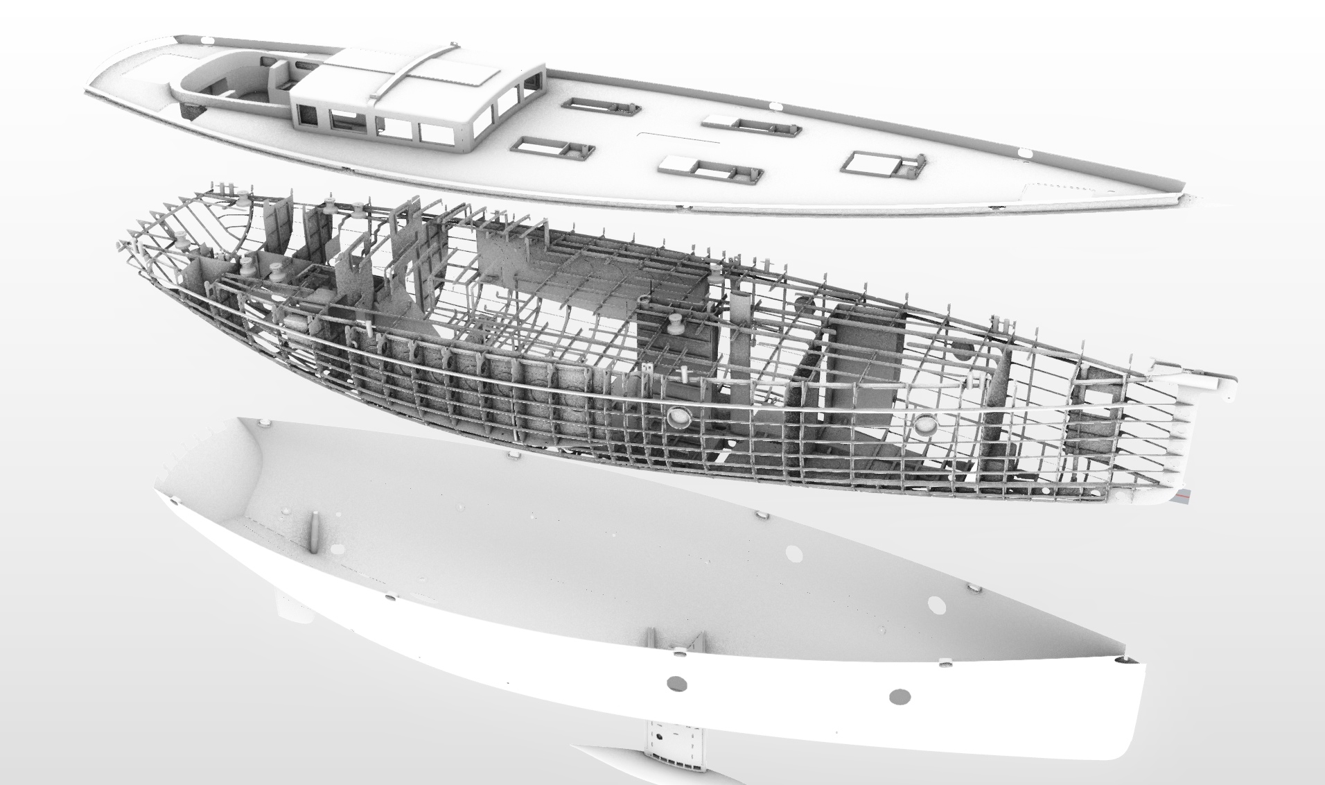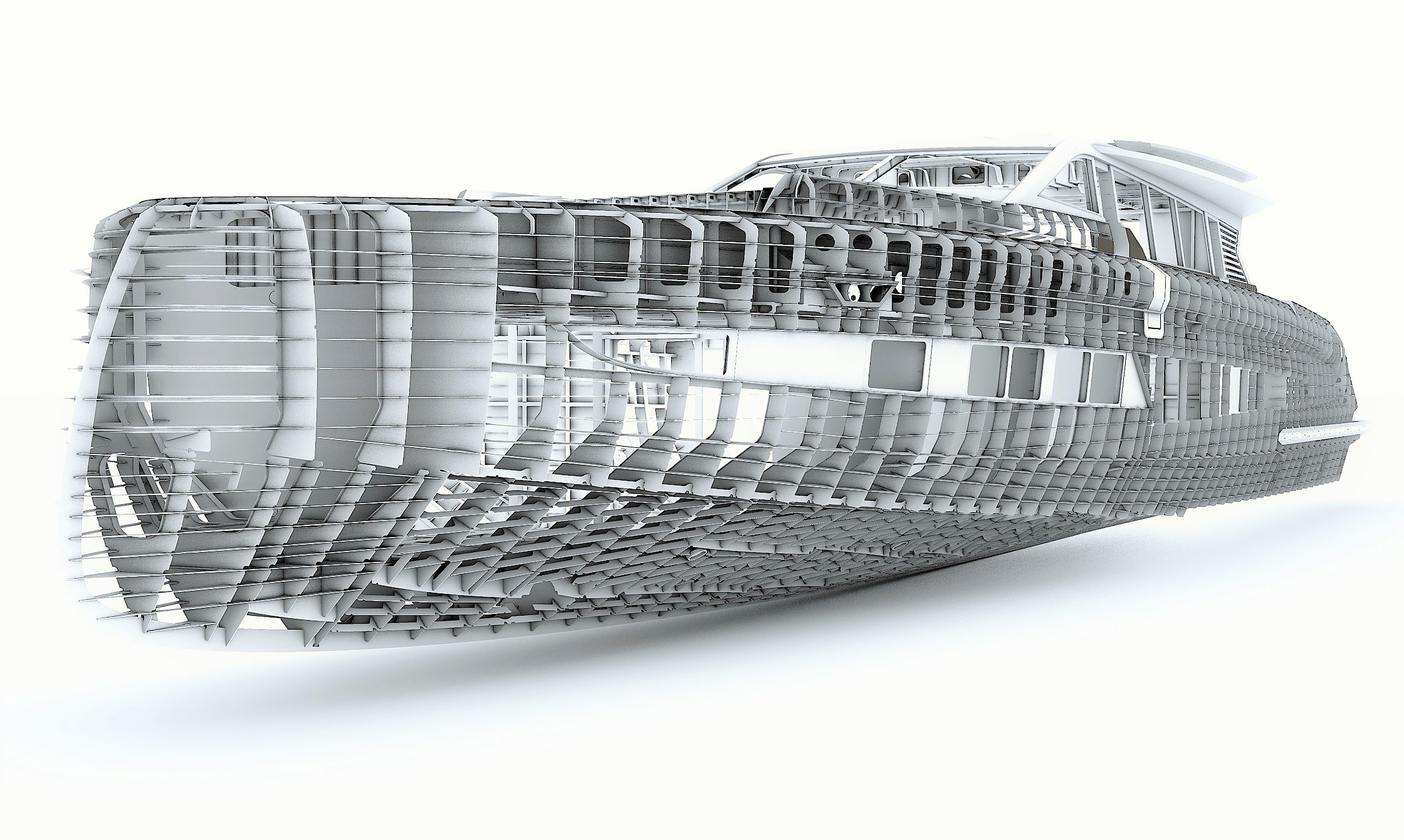
Our output of production files are based on complex ‘’as build’’ 3D models. First item to create into the 3D environment is the accurate surface model of the boat. We can either made this from scratch, based on the lines plan and the general construction drawing or we can improve an existing one that came as a result of the concept stage. After that, we transform the surface model into a solid model, it means all the surfaces are converted into plates with different thicknesses, according to the allocated characteristics form the approved general construction drawing, taking into account the size of the different material sheets and particular demands of the project.


Once the solid model is ready, the next step is to model all the structural components of the boat based on the general construction plan and the specifications of the project. It is in this stage that everything is engineered and put together in a manner that will be possible to construct. The result is a fully detailed model that will contain all the parts as they must be fabricated and assembled to form the construction of the boat, either if they are CNC milled parts or pre-defined standardized profiles. Everything is organized on a specific product hierarchy and each part will have allocated information about material or type of profile to be used.
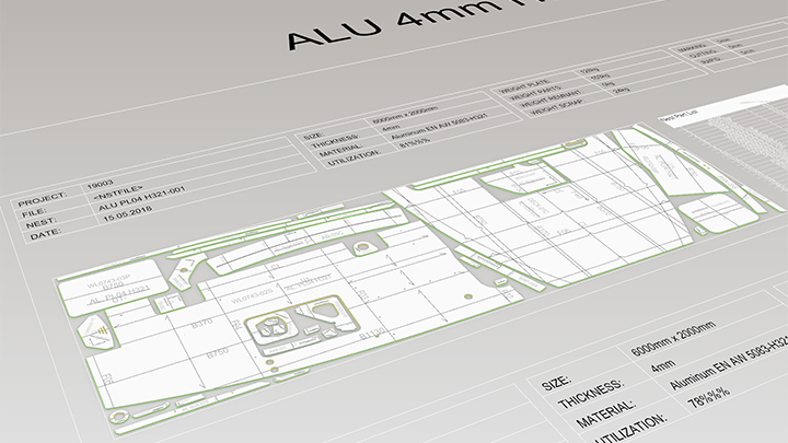
We prepper the parts that will be cut at the CNC in two stages. First is to obtain the expansions – 2D contour projections of all the parts unfolded. In this stage, we analyze simultaneously if a surface needs or not bending and/or forming template and depending of the case, all the parts generated will have marking lines and bending information.
The second stage is to make the nest files – arranging all the expanded parts in the most efficient way possible within the stock plate size. The output consists of a drawing with AutoCAD entities, all of them will be placed on the corresponding layer representing a specific operation.


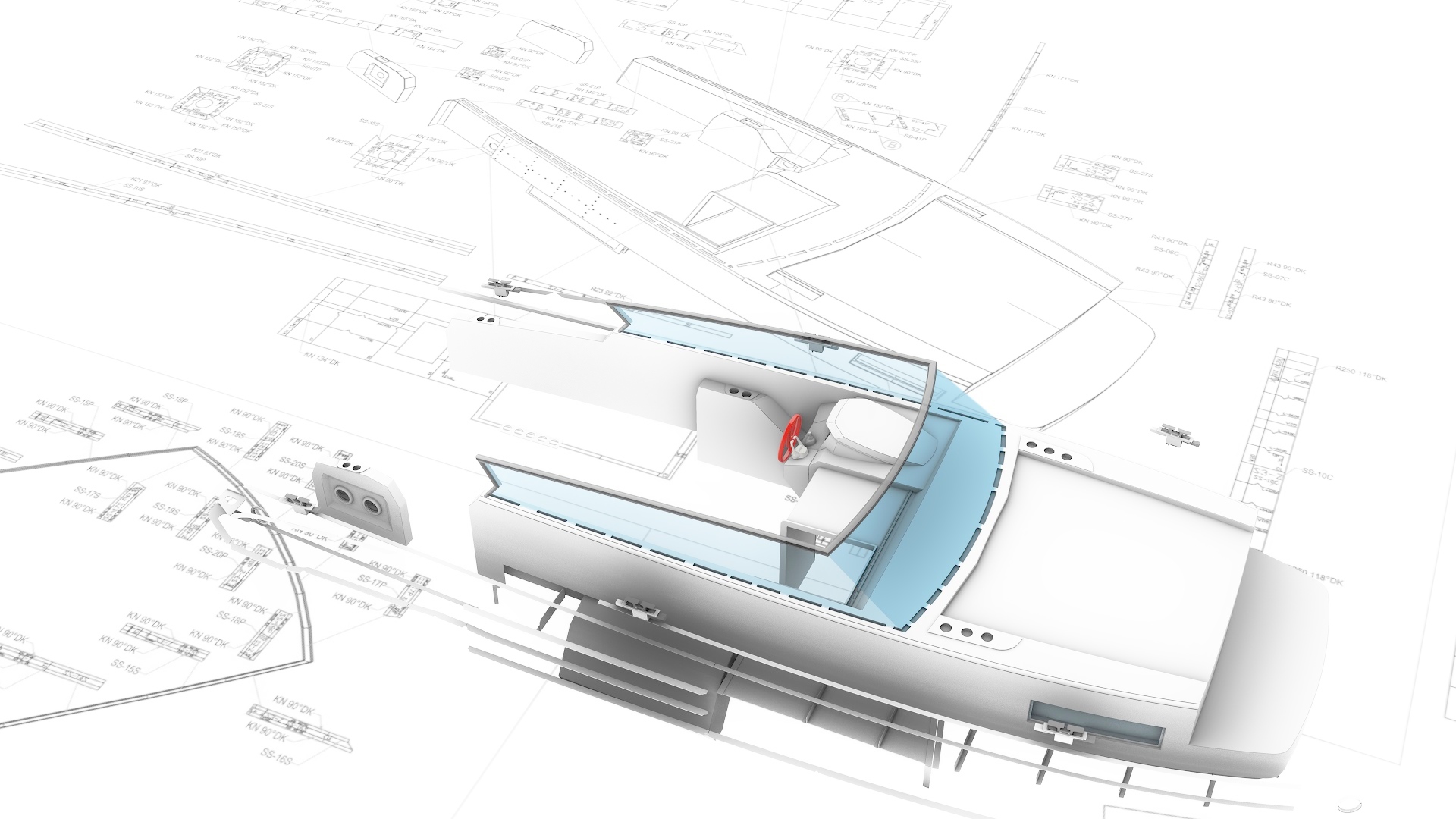
This is the step where we generate all the workshop and assembly drawings plus the associated files that will show how the CNC milled parts and the standardized profiles need to be prepared and assembled together.
The output will consist of:
– Transverse construction drawing
– Longitudinal construction drawing